Integrator-based Filters
We can convert passive RLC filters into integrator-based active filters in a systematic way using signal flow graphs.
Contents
Signal Flow Graphs
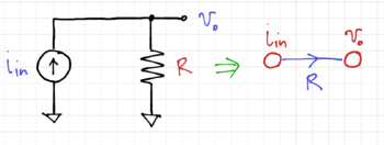
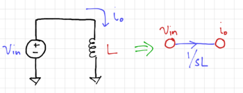
Signal flow graphs (SFGs) are topological representations of electrical circuits with two components: (1) nodes, and (2) branches. Any network that can be described by a set of linear differential equations can be represented by a SFG. In a SFG, the nodes represent the variables, e.g. voltages or currents, and the branches represent transfer functions between these node variables, specified by branch multiplication factors (BMFs). These BMFs are obtained from Kirchhoff's equations (KVL and KCL). Note that the branches are directed, as indicated by the arrows. Figs. 1-3 shows a few examples of SFG nodes and branches.
Useful SFG Properties
We can use the following properties to transform signal flow graphs into forms that can allow us to convert passive RLC filters into its active integrator-based counterparts.
Parallel Branches
For two or more parallel branches between two nodes in the same direction, as seen in Fig. 4, the effective branch multiplication factor becomes:
-
(1)
-
Node Absorption
We can also remove intermediate nodes as shown in Fig. 5:
-
(2)
-
Branch Scaling
Node values in Fig. 6 can be scaled by a factor , but with the corresponding changes on the incoming and outgoing branch:
-
(3)
-
Loops
For the loop shown in Fig. 7, we get:
-
(4)
-


