Consider the RC filter shown in Fig. 1. To convert this passive filter into its active equivalent, we can go through the following steps:
 Figure 1: A passive RC filter. |
Step 1: Name all the voltages and current
All the component voltages and currents are named, as seen in Fig. 1.
Step 2: Use KCL/KVL to obtain the integrator forms
We can get the integrator forms of the reactive components by writing the capacitor voltages as:
-
 |
|
(1)
|
And the inductor currents as:
-
 |
|
(2)
|
Thus, for the simple RC filter, we can write out the voltages as:
-
 |
|
(3)
|
And the currents as:
-
 |
|
(4)
|
Step 3: Construct the SFG
To systematically construct the signal flow graph, let us create the voltage nodes on the top row, and below them, their corresponding current nodes, as shown in Fig. 2. We can then add the branches, starting with the capacitor branch in its integrator form. We then get one possible SFG (Fig. 2).
 Figure 2: The signal flow graph from KCL and KVL equations. |
Step 4: Normalization
The normalization step converts all the current nodes into voltage nodes using a scaling resistance,  , as shown in Fig. 3, converting
  and
and  into
into  and
and  .
.
 Figure 3: The normalized signal flow graph. |
We can then simplify the SFG by combining nodes  and
and  as seen in Fig. 4, and by choosing
  . We then get the SFG in Fig. 5.
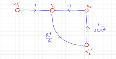 Figure 4: The simplified signal flow graph. |
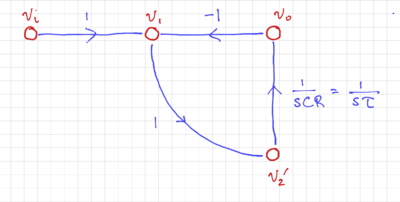 Figure 5: The signal flow graph with . |
We then convert the SFG into its integrator-based equivalent, as shown in Fig. 6. By inverting the input, i.e. multiplying the input by  (Fig. 7), and moving the summation into a two-input integrator (Fig. 8), we can easily match this structure to a 2-input op-amp-based integrator (which is presented here), as shown in Fig. 9.
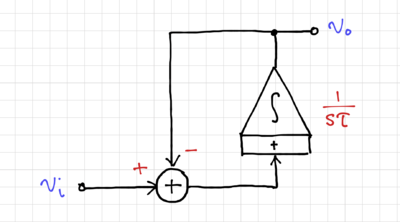 Figure 6: The integrator-based equivalent active filter. |
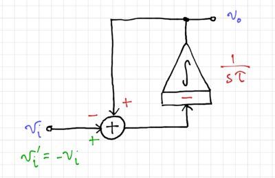 Figure 7: Inverting the input to match an inverting integrator. |
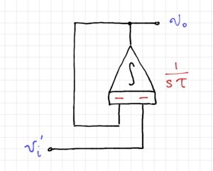 Figure 8: Moving the summation into the integrator. |
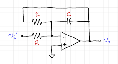 Figure 9: The active filter using operational amplifiers. |
The transfer function, as expected, is equal to:
-
 |
|
(5)
|
We can also calculate the total integrated output noise (as derived here):
-
 |
|
(6)
|


