229-A2.1
Activity: Nonlinearity in Circuits
- Instructions: This activity is structured as a tutorial with a design problem at the end. Should you have any questions, clarifications, or issues, please contact your instructor as soon as possible.
- At the end of this activity, the student should be able to:
- Understand and observe the effects of nonlinearity in electronic circuits.
Visualizing Nonlinearity
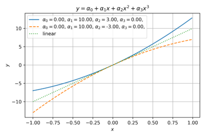
Let us examine the effects of varying the coefficients of the power series model of our transfer function. Fig. 1 shows the an even function with only second order coefficients. This is typical of ideal square-law single-ended MOS amplifiers where a quadratic term dominates.
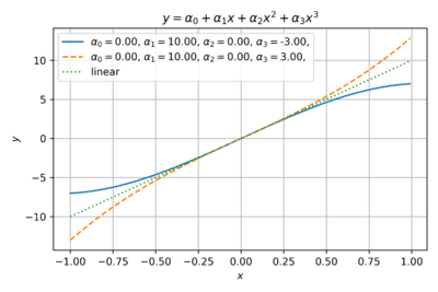
Fig. 2 shows an odd function with only third order coefficients. This is a good estimate for differential circuits, where the common-mode terms cancel out. For example, the outputs of a differential amplifier can be expressed as:
-
(1)
-
-
(2)
-
Then the differential output is:
-
(3)
-
We can also see from Fig. 2 that the negative third (and other odd) order coefficients model the output saturation in real amplifiers as the output level approaches the supply voltages. Thus, in most cases, the third order nonlinearity dominates.


