Difference between revisions of "Filter Families"
| Line 7: | Line 7: | ||
* [[Elliptic Filters]] | * [[Elliptic Filters]] | ||
* [[Bessel Filters]] | * [[Bessel Filters]] | ||
| + | |||
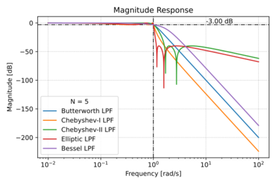
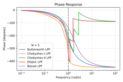
| + | Figs. 1-4 show a quick summary of the characteristics of the four filter families listed above. | ||
| + | |||
| + | {| | ||
| + | |[[File:Filters pz plot.svg|thumb|400px|Figure 1: Pole-zero plots.]] | ||
| + | |[[File:Filters mag.svg|thumb|400px|Figure 2: Low-pass filter magnitude response.]] | ||
| + | |- | ||
| + | |[[File:Filters phase.svg|thumb|400px|Figure 3: Low-pass filter phase response.]] | ||
| + | |[[File:Filters group delay.svg|thumb|400px|Figure 4: Low-pass filter group delay.]] | ||
| + | |- | ||
| + | |} | ||
Revision as of 11:33, 18 March 2021
The location of the poles and zeros of a filter transfer function determines both the magnitude and phase response of that filter. Thus, one important filter metric is the filter order, which specifies the order of the polynomial in the denominator of the transfer function, i.e. the number of poles. Let us look at several filter families, where each family has a particular scheme for pole and zero placement, resulting in certain unique characteristics. Though there are other filter families, we will focus on these four families: (1) Butterworth Filters, (2) Chebyshev Filters, (3) Elliptic Filters, and (4) Bessel Filters.
We will start with low-pass filters, but we can easily convert low-pass filters to their high-pass and band-pass counterparts, with the same characteristics as their low-pass equivalents.
Figs. 1-4 show a quick summary of the characteristics of the four filter families listed above.


