Difference between revisions of "Integrators"
| (13 intermediate revisions by the same user not shown) | |||
| Line 1: | Line 1: | ||
== The Ideal Integrator == | == The Ideal Integrator == | ||
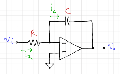
| − | The ideal integrator, shown in Fig. 1, with symbol shown in Fig. 2, makes use of an ideal operational amplifier with <math>A_v\rightarrow\infty</math>, <math>R_i\rightarrow\infty</math>, and <math>R_o=0</math>. The current through the resistor, <math>i_R</math>, can be expressed as: | + | The ideal integrator, shown in Fig. 1, with symbol shown in Fig. 2, makes use of an ideal operational amplifier with <math>A_v\rightarrow\infty</math>, <math>R_i\rightarrow\infty</math>, and <math>R_o=0</math>. |
| + | |||
| + | {| | ||
| + | |[[File:Integrator ideal.png|thumb|400px|Figure 1: The op-amp-based ideal integrator.]] | ||
| + | |[[File:Integrator symbol.png|thumb|300px|Figure 2: The symbol for an integrator.]] | ||
| + | |- | ||
| + | |} | ||
| + | |||
| + | The current through the resistor, <math>i_R</math>, can be expressed as: | ||
{{NumBlk|::|<math> | {{NumBlk|::|<math> | ||
| Line 27: | Line 35: | ||
* The unity gain frequency is equal to <math>\omega_0</math>, and | * The unity gain frequency is equal to <math>\omega_0</math>, and | ||
* The phase at the unity gain frequency is exactly <math>-90^\circ</math>. | * The phase at the unity gain frequency is exactly <math>-90^\circ</math>. | ||
| + | |||
| + | {| | ||
| + | |[[File:Integrator ideal mag.svg|thumb|500px|Figure 3: Magnitude response of an ideal integrator with <math>\omega_0 = 1\,\mathrm{\tfrac{rad}{s}}</math>.]] | ||
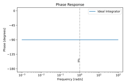
| + | |[[File:Integrator ideal phase.svg|thumb|500px|Figure 4: Phase response of an ideal integrator with <math>\omega_0 = 1\,\mathrm{\tfrac{rad}{s}}</math>.]] | ||
| + | |- | ||
| + | |} | ||
Rewriting the transfer function as: | Rewriting the transfer function as: | ||
| Line 40: | Line 54: | ||
</math>|{{EquationRef|6}}}} | </math>|{{EquationRef|6}}}} | ||
| − | Since <math>R\left(\omega\right) = 0</math>. Fig. 5 shows a | + | Since <math>R\left(\omega\right) = 0</math>. Fig. 5 shows a two-input integrator, with output voltage: |
{{NumBlk|::|<math> | {{NumBlk|::|<math> | ||
v_o\left(s\right) = -\frac{1}{s\cdot R_1 C}\cdot v_1\left(s\right) -\frac{1}{s\cdot R_2 C}\cdot v_2\left(s\right) | v_o\left(s\right) = -\frac{1}{s\cdot R_1 C}\cdot v_1\left(s\right) -\frac{1}{s\cdot R_2 C}\cdot v_2\left(s\right) | ||
</math>|{{EquationRef|7}}}} | </math>|{{EquationRef|7}}}} | ||
| + | |||
| + | {| | ||
| + | |[[File:Integrator 2 input.png|thumb|400px|Figure 5: A two-input op-amp integrator.]] | ||
| + | |- | ||
| + | |} | ||
== Integrator Noise == | == Integrator Noise == | ||
| Line 52: | Line 71: | ||
v_o\left(s\right) = -\frac{1}{s\cdot R_1 C}\cdot v_i\left(s\right) -\frac{1}{s\cdot R_2 C}\cdot v_o\left(s\right) | v_o\left(s\right) = -\frac{1}{s\cdot R_1 C}\cdot v_i\left(s\right) -\frac{1}{s\cdot R_2 C}\cdot v_o\left(s\right) | ||
</math>|{{EquationRef|8}}}} | </math>|{{EquationRef|8}}}} | ||
| + | |||
| + | {| | ||
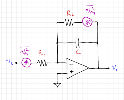
| + | |[[File:Integrator noise.png|thumb|400px|Figure 6: Resistor thermal noise generators in an integrator.]] | ||
| + | |- | ||
| + | |} | ||
Ignoring the noise from the amplifier, the output noise of the integrator in Fig. 6 can be expressed as: | Ignoring the noise from the amplifier, the output noise of the integrator in Fig. 6 can be expressed as: | ||
| Line 75: | Line 99: | ||
== Integrator Non-Idealities == | == Integrator Non-Idealities == | ||
| − | In practice, integrators are limited by the characteristics of non-ideal amplifiers: (1) finite gain at DC, and (2) non-dominant amplifier poles. | + | In practice, integrators are limited by the characteristics of non-ideal amplifiers: (1) finite gain at DC, and (2) non-dominant amplifier poles. Let us look at the effects of these non-idealities one at a time. |
=== Finite Gain === | === Finite Gain === | ||
| Line 84: | Line 108: | ||
</math>|{{EquationRef|11}}}} | </math>|{{EquationRef|11}}}} | ||
| − | The magnitude and phase response of this non-ideal integrator is shown in Figs. 7 and 8. Note that the integrator quality factor now becomes finite: | + | The magnitude and phase response of this non-ideal integrator is shown in Figs. 7 and 8. |
| + | |||
| + | {| | ||
| + | |[[File:Integrator a mag.svg|thumb|500px|Figure 7: The magnitude response of an integrator with a finite-gain amplifier.]] | ||
| + | |[[File:Integrator a phase.svg|thumb|500px|Figure 8: The phase response of an integrator with a finite-gain amplifier.]] | ||
| + | |- | ||
| + | |} | ||
| + | |||
| + | Note that the integrator quality factor now becomes finite: | ||
{{NumBlk|::|<math> | {{NumBlk|::|<math> | ||
| Line 90: | Line 122: | ||
</math>|{{EquationRef|12}}}} | </math>|{{EquationRef|12}}}} | ||
| + | The phase at <math>\omega=\omega_0</math> is then: | ||
| + | |||
| + | {{NumBlk|::|<math> | ||
| + | \angle \left. H\left(s\right) \right|_{\omega=\omega_0} = -\tan^{-1} \left. \left(\frac{\omega}{\omega_0}\cdot a\right)\right|_{\omega=\omega_0} = -\tan^{-1} a | ||
| + | </math>|{{EquationRef|13}}}} | ||
| + | Thus, if <math>a</math> is finite, <math>\angle \left. H\left(s\right) \right|_{\omega=\omega_0}</math> will approach, but will never be equal to <math>-90^\circ</math>, resulting in a ''phase lead''. For example, if <math>a=100</math>, we get <math>\angle \left. H\left(s\right) \right|_{\omega=\omega_0}=-89.427^\circ</math>, and <math>a=1\times 10^6</math> will result in <math>\angle \left. H\left(s\right) \right|_{\omega=\omega_0}=-89.999427^\circ</math>. | ||
=== Non-Dominant Poles === | === Non-Dominant Poles === | ||
| + | The transfer function of an integrator using an amplifier with infinite gain but with non-dominant poles can be expressed as: | ||
| + | |||
| + | {{NumBlk|::|<math> | ||
| + | H\left(s\right) = \frac{1}{\frac{s}{\omega_0} \cdot \left(1+\frac{s}{p_2}\right)\cdot \left(1+\frac{s}{p_3}\right) \cdots} | ||
| + | </math>|{{EquationRef|14}}}} | ||
| + | |||
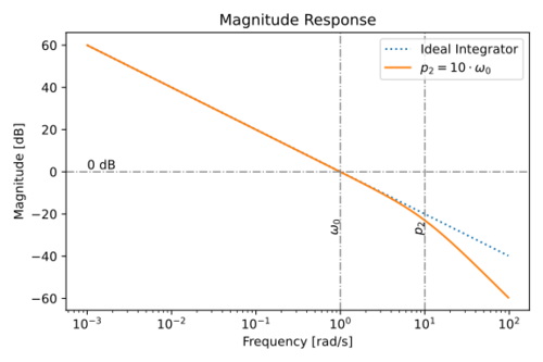
| + | The magnitude and phase response of this non-ideal integrator is shown in Figs. 9 and 10. | ||
| + | |||
| + | {| | ||
| + | |[[File:Integrator p2 mag.svg|thumb|500px|Figure 9: The magnitude response of an integrating using an amplifier with a non-dominant pole, <math>p_2</math>.]] | ||
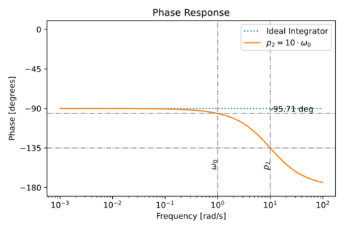
| + | |[[File:Integrator p2 phase.svg|thumb|500px|Figure 10: The phase response of an integrating using an amplifier with a non-dominant pole, <math>p_2</math>.]] | ||
| + | |- | ||
| + | |} | ||
| + | |||
| + | The phase at the unity gain frequency is then equal to: | ||
| + | |||
| + | {{NumBlk|::|<math> | ||
| + | \angle \left. H\left(s\right) \right|_{\omega=\omega_0} = -90 -\tan^{-1} \left(\frac{\omega_0}{p_2}\right) - \tan^{-1} \left(\frac{\omega_0}{p_3}\right) -\ldots | ||
| + | </math>|{{EquationRef|15}}}} | ||
| + | |||
| + | Note that the non-dominant poles contribute to the integrator ''phase lag''. | ||
| + | |||
| + | In a real integrator, the effects (phase lead) of the amplifier finite gain can cancel out the effects (phase lag) of the non-dominant poles! Given the transfer function of the integrator with an amplifier that has both finite gain and non-dominant poles: | ||
| + | |||
| + | {{NumBlk|::|<math> | ||
| + | H\left(s\right) = \frac{a}{\left(1 + s\frac{a}{\omega_0}\right) \cdot \left(1+\frac{s}{p_2}\right)\cdot \left(1+\frac{s}{p_3}\right) \cdots} | ||
| + | </math>|{{EquationRef|16}}}} | ||
| + | |||
| + | If we assume that <math>\omega_0 \ll p_2, p_3, \ldots</math> and <math>a \gg 1</math>, we can then rewrite the transfer function as: | ||
| + | |||
| + | {{NumBlk|::|<math> | ||
| + | \begin{align} | ||
| + | \left. H\left(j\omega\right) \right|_{\omega=\omega_0} & = \frac{1}{\left(\frac{1}{a} + \frac{j\omega_0}{\omega_0}\right) \cdot \left(1 + \frac{j\omega_0}{p_2}\right) \cdot \left(1 + \frac{j\omega_0}{p_3}\right) + \cdots} \\ | ||
| + | & = \frac{1}{\left(\frac{1}{a} - \frac{\omega_0}{p_2} + j + \frac{j\omega_0}{a\cdot p_2}\right) \cdot \left(1 + \frac{j\omega_0}{p_3}\right) + \cdots} \approx \frac{1}{\left(\frac{1}{a} - \frac{\omega_0}{p_2} + j \right) \cdot \left(1 + \frac{j\omega_0}{p_3}\right) + \cdots}\\ | ||
| + | & \approx \frac{1}{\left(\frac{1}{a} - \frac{\omega_0}{p_2} + j + \frac{j\omega_0}{a\cdot p_3} - \frac{j\omega_0^2}{p_2\cdot p_3} - \frac{\omega_0}{p_3}\right)\cdots} \approx \frac{1}{\left(\frac{1}{a} - \frac{\omega_0}{p_2} - \frac{\omega_0}{p_3} + j\right)\cdots} \\ | ||
| + | & \approx \frac{1}{\left(\frac{1}{a} - \frac{\omega_0}{p_2} - \frac{\omega_0}{p_3} - \ldots \right) + j} \\ | ||
| + | & \approx \frac{1}{\left(\frac{1}{a} -\sum\limits_{i=2}^N \frac{\omega_0}{p_i} \right) + j} | ||
| + | \end{align} | ||
| + | </math>|{{EquationRef|17}}}} | ||
| + | |||
| + | For <math>N</math> non-dominant poles. The integrator quality factor is then equal to: | ||
| + | |||
| + | {{NumBlk|::|<math> | ||
| + | Q \approx \frac{1}{\frac{1}{a} -\sum\limits_{i=2}^N \frac{\omega_0}{p_i}} | ||
| + | </math>|{{EquationRef|18}}}} | ||
| + | |||
| + | As expected, the effect of finite gain can be cancelled out by the effect of the non-dominant poles. | ||
=== Capacitor Non-Idealities === | === Capacitor Non-Idealities === | ||
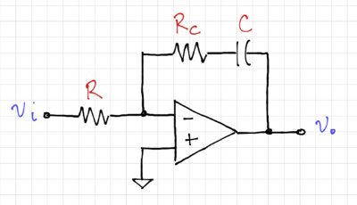
| + | For lossy capacitors, modeled in Fig. 11 as an ideal capacitor in series with a resistor, <math>R_c</math>, the integrator transfer function becomes: | ||
| + | |||
| + | {{NumBlk|::|<math> | ||
| + | \begin{align} | ||
| + | H\left(s\right) = \frac{v_o}{v_i} & = -\left(R_c + \frac{1}{sC} \right)\cdot \frac{1}{R} = -\frac{1}{sRC}\cdot \left(1 + sR_c C\right) \\ | ||
| + | & = -\frac{\omega_0}{s}\cdot \left(1 + sR_c C\right) = -\frac{\omega_0}{j\omega}\cdot \left(1 + j\omega R_c C\right) \\ | ||
| + | & = -\frac{\omega_0}{j\omega}\cdot \frac{1 + \omega^2 R_c^2 C^2 }{1 - j\omega R_c C} | ||
| + | \end{align} | ||
| + | </math>|{{EquationRef|19}}}} | ||
| + | |||
| + | {| | ||
| + | |[[File:Integrator lossy C.png|thumb|400px|Figure 11: An integrator with a lossy capacitor.]] | ||
| + | |- | ||
| + | |} | ||
| + | |||
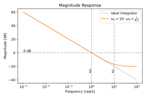
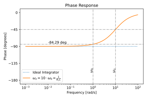
| + | The magnitude and phase response is shown in Figs. 12 and 13. | ||
| + | |||
| + | {| | ||
| + | |[[File:Integrator lossy C mag.svg|thumb|500px|Figure 12: Magnitude response of an integrator with a lossy capacitor.]] | ||
| + | |[[File:Integrator lossy C phase.svg|thumb|500px|Figure 13: Magnitude response of an integrator with a lossy capacitor.]] | ||
| + | |- | ||
| + | |} | ||
| + | |||
| + | Notice the phase lead introduced by the zero due to <math>R_c</math>. At <math>\omega=\omega_0</math>: | ||
| + | |||
| + | {{NumBlk|::|<math> | ||
| + | \begin{align} | ||
| + | H\left(j\omega_0\right) & = -\frac{1}{j}\cdot \frac{1 + \omega_0^2 R_c^2 C^2 }{1 - j\omega_0 R_c C} = \frac{-\left( 1 + \omega_0^2 R_c^2 C^2 \right)}{j + \omega_0 R_c C} \\ | ||
| + | & = \frac{-1}{j\frac{1}{1 + \omega_0^2 R_c^2 C^2} + \frac{\omega_0 R_c C}{1 + \omega_0^2 R_c^2 C^2}} | ||
| + | \end{align} | ||
| + | </math>|{{EquationRef|20}}}} | ||
| + | |||
| + | The integrator quality factor can then be written as: | ||
| + | |||
| + | {{NumBlk|::|<math> | ||
| + | Q = \frac{1}{\omega_0 R_c C} = \frac{RC}{R_c C} = \frac{R}{R_c} | ||
| + | </math>|{{EquationRef|21}}}} | ||
| + | |||
| + | Thus, a non-zero <math>R_c</math> degrades the integrator quality factor, but in typical implementations, the amplifier non-idealities will dominate. | ||
| + | |||
| + | == <math>G_m\text{-}C</math> Integrators == | ||
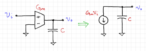
| + | An alternative implementation of an integrator is to use transconductances, which drive constant current into capacitors, as shown in Fig. 14. | ||
| + | |||
| + | {| | ||
| + | |[[File:Integrator gm c.png|thumb|500px|Figure 14: A <math>G_m\text{-}C</math> integrator.]] | ||
| + | |- | ||
| + | |} | ||
| + | |||
| + | We can write the output voltage as: | ||
| + | |||
| + | {{NumBlk|::|<math> | ||
| + | v_o = -\frac{1}{sC}\cdot G_m\cdot v_i = -\frac{1}{s\cdot \tau} \cdot v_i = -\frac{\omega_0}{s} \cdot v_i | ||
| + | </math>|{{EquationRef|22}}}} | ||
| + | |||
| + | Where <math>\omega_0 = \tfrac{1}{\tau} = \tfrac{G_m}{C}</math>. This type of integrator is ideal in cases where the loads are capacitive, e.g. in CMOS circuits, and are much simpler than op-amp-based integrators since <math>G_m\text{-}C</math> integrators are open-loop circuits without feedback. In general, real transconductance amplifiers will have transconductances that vary with frequency, <math>G_m = G_m\left(s\right) = G_m\left(j\omega\right)</math>, thus also affecting the phase at <math>\omega_0</math>, similar to op-amp-based integrators. | ||
| + | |||
| + | == Summary == | ||
| + | The quality factor of the integrator is reduced by: | ||
| + | * The finite gain of the amplifier, | ||
| + | * The presence of amplifier non-dominant poles, and | ||
| + | * The loss of passive reactive components, e.g. capacitors. | ||
| + | |||
| + | Note that both the finite amplifier gain and the lossy capacitor introduces a phase lead, and the presence of non-dominant poles results in a phase lag. | ||
Latest revision as of 11:30, 5 April 2021
Contents
The Ideal Integrator
The ideal integrator, shown in Fig. 1, with symbol shown in Fig. 2, makes use of an ideal operational amplifier with , , and .
The current through the resistor, , can be expressed as:
-
(1)
-
Thus, we can write the integrator output voltage, , as:
-
(2)
-
In the Laplace domain:
-
(3)
-
Or equivalently:
-
(4)
-
The magnitude and phase response of an ideal integrator is shown in Figs. 3 and 4. A key feature to note in ideal integrators is the fact that:
- The unity gain frequency is equal to , and
- The phase at the unity gain frequency is exactly .
Rewriting the transfer function as:
-
(5)
-
We can then define the quality factor of an ideal integrator:
-
(6)
-
Since . Fig. 5 shows a two-input integrator, with output voltage:
-
(7)
-
Integrator Noise
Fig. 6 shows an integrator where the output is fed back to one of its inputs, giving us:
-
(8)
-
Ignoring the noise from the amplifier, the output noise of the integrator in Fig. 6 can be expressed as:
-
(9)
-
The total integrated noise is then:
-
(10)
-
Integrator Non-Idealities
In practice, integrators are limited by the characteristics of non-ideal amplifiers: (1) finite gain at DC, and (2) non-dominant amplifier poles. Let us look at the effects of these non-idealities one at a time.
Finite Gain
The transfer function of an integrator using an amplifier with finite gain, , can be written as:
-
(11)
-
The magnitude and phase response of this non-ideal integrator is shown in Figs. 7 and 8.
Note that the integrator quality factor now becomes finite:
-
(12)
-
The phase at is then:
-
(13)
-
Thus, if is finite, will approach, but will never be equal to , resulting in a phase lead. For example, if , we get , and will result in .
Non-Dominant Poles
The transfer function of an integrator using an amplifier with infinite gain but with non-dominant poles can be expressed as:
-
(14)
-
The magnitude and phase response of this non-ideal integrator is shown in Figs. 9 and 10.
The phase at the unity gain frequency is then equal to:
-
(15)
-
Note that the non-dominant poles contribute to the integrator phase lag.
In a real integrator, the effects (phase lead) of the amplifier finite gain can cancel out the effects (phase lag) of the non-dominant poles! Given the transfer function of the integrator with an amplifier that has both finite gain and non-dominant poles:
-
(16)
-
If we assume that and , we can then rewrite the transfer function as:
-
(17)
-
For non-dominant poles. The integrator quality factor is then equal to:
-
(18)
-
As expected, the effect of finite gain can be cancelled out by the effect of the non-dominant poles.
Capacitor Non-Idealities
For lossy capacitors, modeled in Fig. 11 as an ideal capacitor in series with a resistor, , the integrator transfer function becomes:
-
(19)
-
The magnitude and phase response is shown in Figs. 12 and 13.
Notice the phase lead introduced by the zero due to . At :
-
(20)
-
The integrator quality factor can then be written as:
-
(21)
-
Thus, a non-zero degrades the integrator quality factor, but in typical implementations, the amplifier non-idealities will dominate.
Integrators
An alternative implementation of an integrator is to use transconductances, which drive constant current into capacitors, as shown in Fig. 14.
We can write the output voltage as:
-
(22)
-
Where . This type of integrator is ideal in cases where the loads are capacitive, e.g. in CMOS circuits, and are much simpler than op-amp-based integrators since integrators are open-loop circuits without feedback. In general, real transconductance amplifiers will have transconductances that vary with frequency, , thus also affecting the phase at , similar to op-amp-based integrators.
Summary
The quality factor of the integrator is reduced by:
- The finite gain of the amplifier,
- The presence of amplifier non-dominant poles, and
- The loss of passive reactive components, e.g. capacitors.
Note that both the finite amplifier gain and the lossy capacitor introduces a phase lead, and the presence of non-dominant poles results in a phase lag.


