Difference between revisions of "Filter Families"
| (4 intermediate revisions by the same user not shown) | |||
| Line 1: | Line 1: | ||
| − | The location of the poles and zeros of a filter transfer function determines both the magnitude and phase response of that filter. Let us look at several filter ''families'', where each family has a particular scheme for pole and zero placement, resulting in certain unique characteristics. Though there are other filter families, we will focus on these four families: (1) Butterworth Filters, (2) Chebyshev Filters, (3) Elliptic Filters, and (4) Bessel Filters. | + | The location of the poles and zeros of a filter transfer function determines both the magnitude and phase response of that filter. Thus, one important filter metric is the '''filter order''', which specifies the order of the polynomial in the denominator of the transfer function, i.e. the number of poles. Let us look at several filter ''families'', where each family has a particular scheme for pole and zero placement, resulting in certain unique characteristics. Though there are other filter families, we will focus on these four families: (1) Butterworth Filters, (2) Chebyshev Filters, (3) Elliptic Filters, and (4) Bessel Filters. |
| − | + | We will start with low-pass filters, but we can easily convert low-pass filters to their high-pass and band-pass counterparts, with the same characteristics as their low-pass equivalents. | |
| − | + | * [[Butterworth Filters]] | |
| + | * [[Chebyshev Filters]] | ||
| + | * [[Elliptic Filters]] | ||
| + | * [[Bessel Filters]] | ||
| − | + | Figs. 1-4 show a quick summary of the characteristics of the four filter families listed above. | |
| − | + | {| | |
| + | |[[File:Filters pz plot.svg|thumb|400px|Figure 1: Pole-zero plots.]] | ||
| + | |[[File:Filters mag.svg|thumb|400px|Figure 2: Low-pass filter magnitude response.]] | ||
| + | |- | ||
| + | |[[File:Filters phase.svg|thumb|400px|Figure 3: Low-pass filter phase response.]] | ||
| + | |[[File:Filters group delay.svg|thumb|400px|Figure 4: Low-pass filter group delay.]] | ||
| + | |- | ||
| + | |} | ||
| − | == | + | === Step Response === |
| + | If there is phase distortion, not only do we remove the high-frequencies, we also add delays to the individual frequency components in the pass-band as shown in Fig. 5. These delays realign the sinusoids such that the ideal constructive and destructive interactions are no longer preserved, and can lead to ''inter-symbol interference'' or ISI. | ||
| + | {| | ||
| + | |[[File:Filters step response.svg|thumb|400px|Figure 5: Low-pass filter step response.]] | ||
| + | |- | ||
| + | |} | ||
| + | |||
| + | == Summary == | ||
| + | * In general, the higher filter attenuation in the stop-band per pole, the poorer the phase response. | ||
| + | * Tighter group delay specifications for a given attenuation increases the minimum filter order. Note that in cases where the filter is followed by an ADC and DSP, we can digitally correct for phase distortion, and can lower the minimum required filter order. | ||
Latest revision as of 15:04, 24 March 2021
The location of the poles and zeros of a filter transfer function determines both the magnitude and phase response of that filter. Thus, one important filter metric is the filter order, which specifies the order of the polynomial in the denominator of the transfer function, i.e. the number of poles. Let us look at several filter families, where each family has a particular scheme for pole and zero placement, resulting in certain unique characteristics. Though there are other filter families, we will focus on these four families: (1) Butterworth Filters, (2) Chebyshev Filters, (3) Elliptic Filters, and (4) Bessel Filters.
We will start with low-pass filters, but we can easily convert low-pass filters to their high-pass and band-pass counterparts, with the same characteristics as their low-pass equivalents.
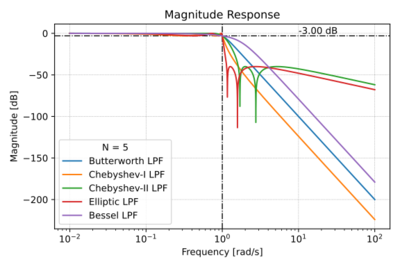
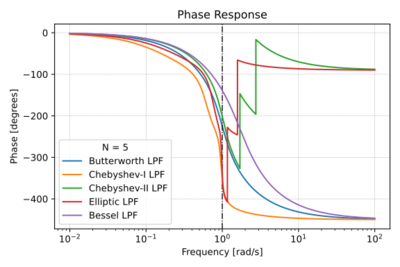
Figs. 1-4 show a quick summary of the characteristics of the four filter families listed above.
Step Response
If there is phase distortion, not only do we remove the high-frequencies, we also add delays to the individual frequency components in the pass-band as shown in Fig. 5. These delays realign the sinusoids such that the ideal constructive and destructive interactions are no longer preserved, and can lead to inter-symbol interference or ISI.
Summary
- In general, the higher filter attenuation in the stop-band per pole, the poorer the phase response.
- Tighter group delay specifications for a given attenuation increases the minimum filter order. Note that in cases where the filter is followed by an ADC and DSP, we can digitally correct for phase distortion, and can lower the minimum required filter order.


