Difference between revisions of "Filter Basics"
Jump to navigation
Jump to search
| Line 14: | Line 14: | ||
== Ideal vs. Practical Filters == | == Ideal vs. Practical Filters == | ||
| + | |||
| + | {| | ||
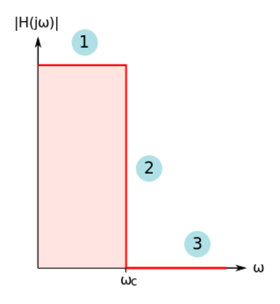
| + | |[[File:Ideal filter.svg|thumb|400px|Figure 6: The ideal low-pass filter magnitude response.]] | ||
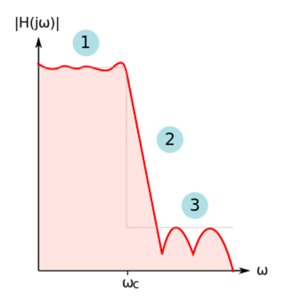
| + | |[[File:Practical filter.svg|thumb|400px|Figure 7: A practical low-pass filter magnitude response.]] | ||
| + | |- | ||
| + | |} | ||
== Magnitude and Frequency Metrics == | == Magnitude and Frequency Metrics == | ||
== Group Delay == | == Group Delay == | ||
Revision as of 16:46, 12 March 2021
Filtering is the oldest and most common type of signal processing, usually in the form of frequency selectivity or phase shaping, or both. Some filter applications include (1) extracting a desired signal from other signals, (2) separating signals from noise, (3) anti-aliasing in analog-to-digital converters or smoothing in digital-to-analog converters, (4) phase equalization, and (5) limiting amplifier bandwidths for reducing noise.
Contents
Filter Types
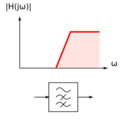
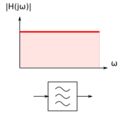
We can classify filters based on frequency range selectivity as: (1) low-pass filters, (2) high-pass filters, (3) band-pass filters, (4) band-stop, band-reject, or notch filters, and (5) all-pass filters used for phase shaping or equalization.


