SFG RLC Filter Example
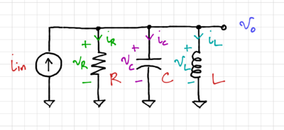
Consider the second-order RLC Filter shown in Fig. 1. Let us use signal flow graphs to convert this passive filter into an equivalent active filter.
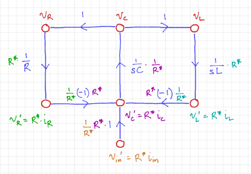
After labeling the node voltages and branch currents, we then express the inductor currents and capacitor voltages as integrator forms, as shown in the signal flow graph in Fig. 2.
We then normalize the signal flow graph to convert the current nodes into voltage nodes, as shown in Figs. 3 and 4.
The integrator-based active filter can then be derived, as seen in Fig. 5, with and .
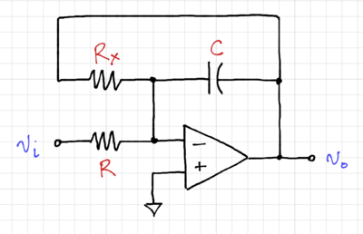
Using signal flow graphs, we have converted the passive RLC band-pass filter to an equivalent inductor-less active filter, composed only of integrators, a gain stage with a gain of , and a summing circuit. In practice, we can combine the summation and the gain into the op-amp circuit, as shown in Fig. 6.
The output is then:
-
(1)
-
Thus, the integrator with time constant and the gain can be combined into a single op-amp circuit with . We will look at a more detailed circuit implementation later, since we still have a few issues left to tackle, such as how to efficiently perform subtraction together with addition.


