Difference between revisions of "Frequency Response Visualization"
Jump to navigation
Jump to search
| Line 6: | Line 6: | ||
|- | |- | ||
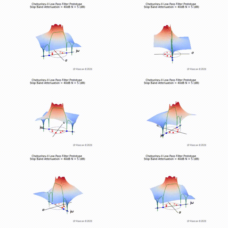
|[[File:Chebyshev2 vid.gif|thumb|400px|Figure 3: The low-pass Chebyshev Type-II filter frequency response.]] | |[[File:Chebyshev2 vid.gif|thumb|400px|Figure 3: The low-pass Chebyshev Type-II filter frequency response.]] | ||
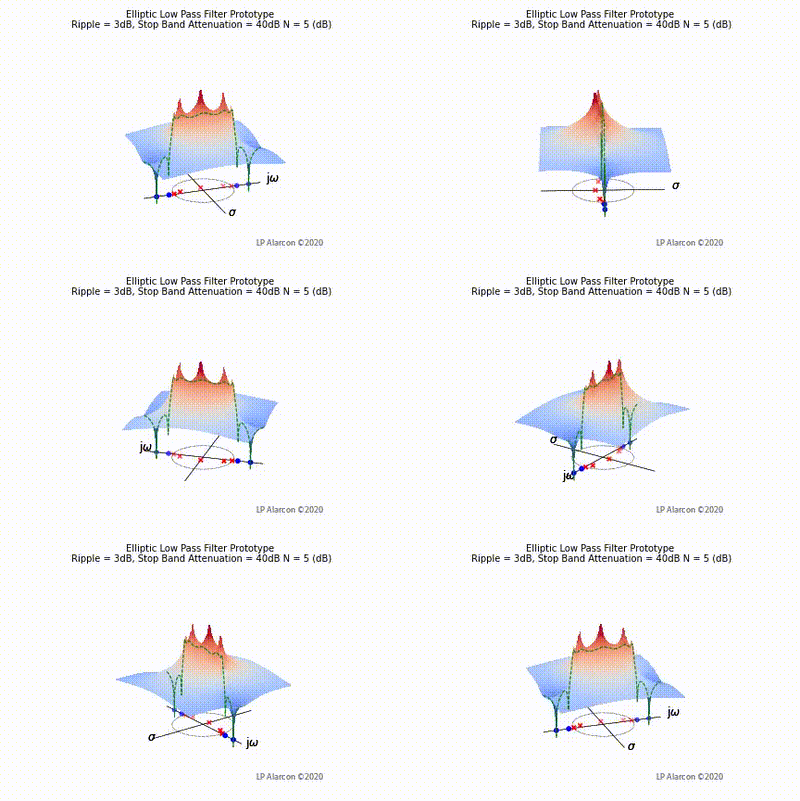
| − | |[[File:Elliptic vid.gif|thumb|400px|Figure | + | |[[File:Elliptic vid.gif|thumb|400px|Figure 4: The low-pass Elliptic filter frequency response.]] |
|- | |- | ||
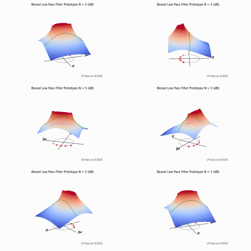
| − | |[[File:Bessel vid.gif|thumb|400px|Figure | + | |[[File:Bessel vid.gif|thumb|400px|Figure 5: The low-pass Bessel filter frequency response.]] |
| | | | ||
|- | |- | ||
|} | |} | ||
Revision as of 00:15, 19 March 2021
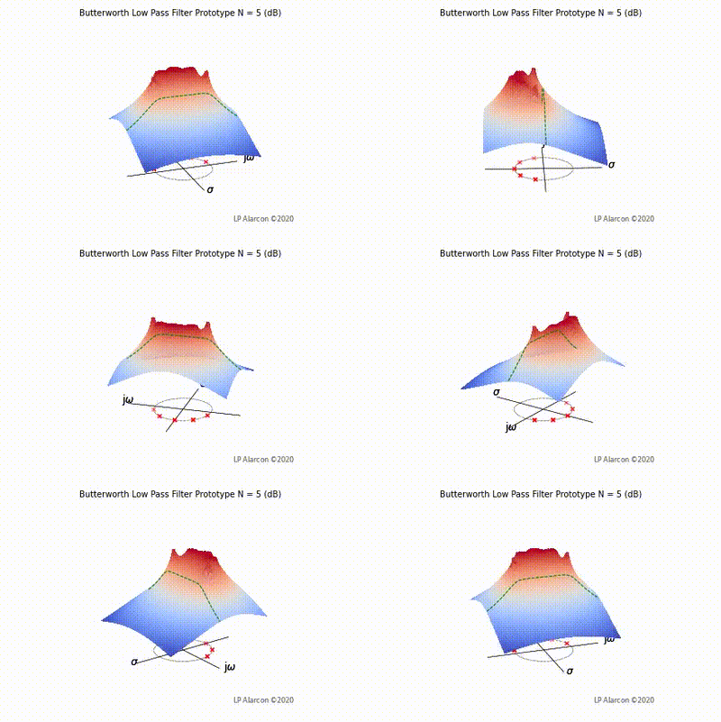
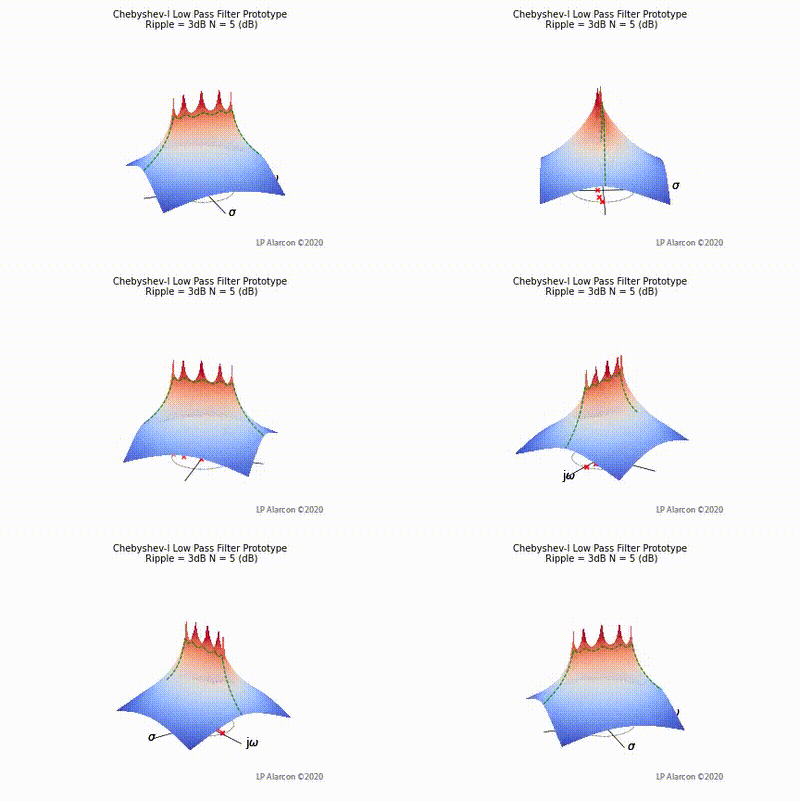
The magnitude response of a linear system is the intersection of the magnitude of the transfer function, , in the -plane and the plane containing the -axis, as shown by the dashed green lines in Figs. 1-4. Note that the poles are the values of that makes , and the zeros are values of that result in .


