Difference between revisions of "Elliptic Filters"
(Created page with "The transfer function of Elliptic filters contain both poles and zeros. Similar to the Chebyshev Type-I filter, the poles are Elliptic low-pass filter are located inside the u...") |
|||
| (2 intermediate revisions by the same user not shown) | |||
| Line 1: | Line 1: | ||
| − | The transfer function of Elliptic filters contain both poles and zeros. Similar to the Chebyshev Type-I filter, the poles are Elliptic low-pass filter are located inside the unit circle. In addition to its poles, the Elliptic filter also has zeros in its transfer function, and are located on the <math>j\omega</math> axis. This unique combination of poles and zeros results in (1) a transition band shorter than any other filter of the same order, and (2) the poorest phase response relative to the Butterworth and Chebyshev filters. | + | The transfer function of Elliptic filters contain both poles and zeros. Similar to the Chebyshev Type-I filter, the poles are Elliptic low-pass filter are located inside the unit circle. In addition to its poles, the Elliptic filter also has zeros in its transfer function, and are located on the <math>j\omega</math> axis. Note that for even filter orders, the number of finite zeros are equal to the number of poles. However, for odd orders, the number of finite zeros are one less than the number of poles, i.e. one zero is at infinity. This unique combination of poles and zeros results in (1) a transition band shorter than any other filter of the same order, and (2) the poorest phase response relative to the Butterworth and Chebyshev filters. |
The Elliptic filter is sometimes called the Cauer filter or the Zolotarev filter. | The Elliptic filter is sometimes called the Cauer filter or the Zolotarev filter. | ||
| Line 10: | Line 10: | ||
</math>|{{EquationRef|1}}}} | </math>|{{EquationRef|1}}}} | ||
| − | Where <math>N</math> is the filter order, <math>\omega_0</math> is the cut-off frequency, <math>\varepsilon=\sqrt{10^\frac{\delta}{10}-1}</math> is the ripple factor with ripple <math>\delta</math> in dB, <math>\xi</math> is the selectivity factor, and <math>R_N</math> is the elliptic (or Chebyshev) rational function. | + | Where <math>N</math> is the filter order, <math>\omega_0</math> is the cut-off frequency, <math>\varepsilon=\sqrt{10^\frac{\delta}{10}-1}</math> is the ripple factor with ripple <math>\delta</math> in dB, <math>\xi</math> is the selectivity factor that determines the stopband attenuation equal to <math>\left[1+\varepsilon^2 R_N\left(\xi,\xi\right)\right]^{0.5}</math>, and <math>R_N</math> is the elliptic (or Chebyshev) rational function. |
| + | |||
| + | Note that: | ||
| + | * When <math>\xi\rightarrow 0</math>, the Elliptic filter approaches the Chebyshev Type-I filter. | ||
| + | * When <math>\varepsilon\rightarrow 0</math>, the Elliptic filter approaches the Chebyshev Type-II filter. | ||
| + | * When <math>\xi\rightarrow 0</math> and <math>\varepsilon\rightarrow 0</math>, the Elliptic filter approaches the Butterworth filter. | ||
| + | |||
| + | The Elliptic filter characteristics for <math>N=5</math> are shown in Figs. 1-4. | ||
| + | |||
| + | {| | ||
| + | |[[File:Elliptic pz plot.svg|thumb|400px|Figure 1: The low-pass Elliptic filter pole-zero plot for <math>N=5</math>, a pass-band ripple of <math>3\,\text{dB}</math>, and a stop-band attenuation of <math>40\,\text{dB}</math>.]] | ||
| + | |[[File:Elliptic mag.svg|thumb|400px|Figure 2: The low-pass Elliptic filter magnitude response for <math>N=5</math>, a pass-band ripple of <math>3\,\text{dB}</math>, and a stop-band attenuation of <math>40\,\text{dB}</math>.]] | ||
| + | |- | ||
| + | |[[File:Elliptic phase.svg|thumb|400px|Figure 3: The low-pass Elliptic filter phase response for <math>N=5</math>, a pass-band ripple of <math>3\,\text{dB}</math>, and a stop-band attenuation of <math>40\,\text{dB}</math>.]] | ||
| + | |[[File:Elliptic group delay.svg|thumb|400px|Figure 3: The low-pass Elliptic filter group delay for <math>N=5</math>, a pass-band ripple of <math>3\,\text{dB}</math>, and a stop-band attenuation of <math>40\,\text{dB}</math>.]] | ||
| + | |- | ||
| + | |} | ||
Latest revision as of 10:24, 18 March 2021
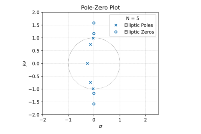
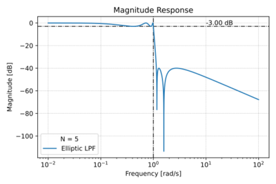
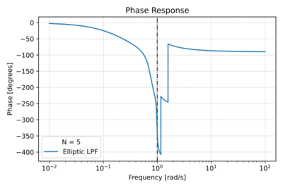
The transfer function of Elliptic filters contain both poles and zeros. Similar to the Chebyshev Type-I filter, the poles are Elliptic low-pass filter are located inside the unit circle. In addition to its poles, the Elliptic filter also has zeros in its transfer function, and are located on the axis. Note that for even filter orders, the number of finite zeros are equal to the number of poles. However, for odd orders, the number of finite zeros are one less than the number of poles, i.e. one zero is at infinity. This unique combination of poles and zeros results in (1) a transition band shorter than any other filter of the same order, and (2) the poorest phase response relative to the Butterworth and Chebyshev filters.
The Elliptic filter is sometimes called the Cauer filter or the Zolotarev filter.
The Low-Pass Elliptic Filter
The magnitude response of the low-pass Elliptic filter is given by:
-
(1)
-
Where is the filter order, is the cut-off frequency, is the ripple factor with ripple in dB, is the selectivity factor that determines the stopband attenuation equal to , and is the elliptic (or Chebyshev) rational function.
Note that:
- When , the Elliptic filter approaches the Chebyshev Type-I filter.
- When , the Elliptic filter approaches the Chebyshev Type-II filter.
- When and , the Elliptic filter approaches the Butterworth filter.
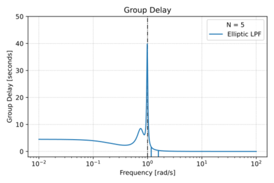
The Elliptic filter characteristics for are shown in Figs. 1-4.


![{\displaystyle \left[1+\varepsilon ^{2}R_{N}\left(\xi ,\xi \right)\right]^{0.5}}](https://en.wikipedia.org/api/rest_v1/media/math/render/svg/915ed92bbd82deb1262017123f38f7903a8776a5)


