Difference between revisions of "Bessel Filters"
Jump to navigation
Jump to search
| (2 intermediate revisions by the same user not shown) | |||
| Line 20: | Line 20: | ||
</math>|{{EquationRef|3}}}} | </math>|{{EquationRef|3}}}} | ||
| − | For <math>k=0,1,\ldots N</math>. | + | For <math>k=0,1,\ldots N</math>. The low-pass Bessel filter characteristics are shown in Figs. 1-4. |
| + | |||
| + | {| | ||
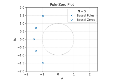
| + | |[[File:Bessel pz plot.svg|thumb|400px|Figure 1: The low-pass Bessel filter pole-zero plot for <math>N=5</math>.]] | ||
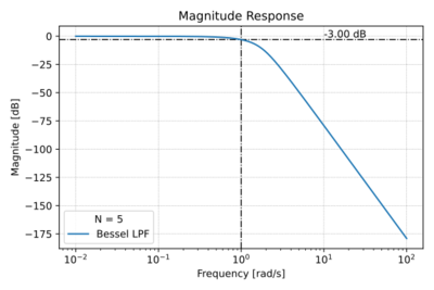
| + | |[[File:Bessel mag.svg|thumb|400px|Figure 2: The low-pass Bessel filter magnitude response for <math>N=5</math>.]] | ||
| + | |- | ||
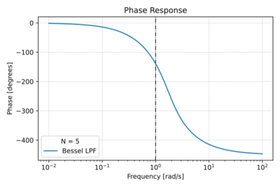
| + | |[[File:Bessel phase.svg|thumb|400px|Figure 3: The low-pass Bessel filter phase response for <math>N=5</math>.]] | ||
| + | |[[File:Bessel group delay.svg|thumb|400px|Figure 4: The low-pass Bessel filter group delay for <math>N=5</math>.]] | ||
| + | |- | ||
| + | |} | ||
Latest revision as of 09:30, 18 March 2021
Bessel filters are all-pole filters with maximally flat pass-bands, maximally flat group delays, and poor "out-of-band" or stop-band attenuation compared to Butterworth, Chebyshev, and Elliptic filters of the same order. Since the group delays are relatively constant in the pass-band, Bessel filters exhibit minimal phase distortion, and hence very little overshoot in its step response.
The Low-Pass Bessel Filter
The transfer function of the low-pass Bessel filter is given by:
-
(1)
-
Where is the filter order, is the cut-off frequnecy, and is the reverse Bessel polynomial, and is equal to:
-
(2)
-
Where:
-
(3)
-
For . The low-pass Bessel filter characteristics are shown in Figs. 1-4.


