Difference between revisions of "Resistor Noise"
| (11 intermediate revisions by the same user not shown) | |||
| Line 2: | Line 2: | ||
== Modeling Thermal Noise in Resistors == | == Modeling Thermal Noise in Resistors == | ||
| − | [[File:R noise model.png|thumb| | + | [[File:R noise model.png|thumb|350px|Figure 1: Resistor noise generators.]] |
Consider the noisy resistor in Fig. 1. We can model this as a noiseless resistor in series with a voltage noise generator, or a noiseless resistor in parallel with a current noise generator. Since we cannot predict the voltage or current noise at any point in time, we can instead specify the noise mean square voltage spectral density over a unit bandwidth, <math>\Delta f</math>: | Consider the noisy resistor in Fig. 1. We can model this as a noiseless resistor in series with a voltage noise generator, or a noiseless resistor in parallel with a current noise generator. Since we cannot predict the voltage or current noise at any point in time, we can instead specify the noise mean square voltage spectral density over a unit bandwidth, <math>\Delta f</math>: | ||
{{NumBlk|::|<math>\overline{v^2_n} = 4kTR \Delta f</math>|{{EquationRef|1}}}} | {{NumBlk|::|<math>\overline{v^2_n} = 4kTR \Delta f</math>|{{EquationRef|1}}}} | ||
| − | Where <math>k</math> is Boltzmann's constant, equal to <math> | + | Where <math>k</math> is Boltzmann's constant, equal to <math>1.38064852 \times 10^{-23}\mathrm{\tfrac{J}{K}}</math> and <math>T</math> is the temperature in Kelvin. The total integrated noise power is then: |
| − | {{NumBlk|::|<math>\overline{v^2_{n,T}} = \int_B \left(\frac{\overline{v^2_n}}{\Delta f}\right) df = \int_B 4kTR df= 4kTRB</math>|{{EquationRef| | + | {{NumBlk|::|<math>\overline{v^2_{n,T}} = \int_B \left(\frac{\overline{v^2_n}}{\Delta f}\right) df = \int_B 4kTR\, df= 4kTRB</math>|{{EquationRef|2}}}} |
Where <math>B</math> is the observation bandwidth. Alternatively, we can specify the total integrated noise power from the noise current generator: | Where <math>B</math> is the observation bandwidth. Alternatively, we can specify the total integrated noise power from the noise current generator: | ||
| − | {{NumBlk|::|<math>\overline{i^2_{n,T}} = 4kTGB = \frac{4kTB}{R}</math>|{{EquationRef| | + | {{NumBlk|::|<math>\overline{i^2_{n,T}} = 4kTGB = \frac{4kTB}{R}</math>|{{EquationRef|3}}}} |
| + | [[File:R spectral density.png|thumb|350px|Figure 2: The resistor noise power spectral density.]] | ||
Thermal noise is ''white'' noise, since <math>\tfrac{\overline{v^2_n}}{\Delta f}=4kTR</math> is constant over frequency, and hence the noise generators have ''white'' power spectral densities, as shown in Fig. 2. Just like any small signal, the shape of the power spectral density can be shaped by the frequency response of the rest of the circuit. | Thermal noise is ''white'' noise, since <math>\tfrac{\overline{v^2_n}}{\Delta f}=4kTR</math> is constant over frequency, and hence the noise generators have ''white'' power spectral densities, as shown in Fig. 2. Just like any small signal, the shape of the power spectral density can be shaped by the frequency response of the rest of the circuit. | ||
| − | Also note that the polarity of the noise generators are intentionally not specified in the symbols, since the noise voltage or current can take on positive or negative values at any given time. | + | Also note that the polarity of the noise generators are intentionally not specified in the symbols shown in Fig. 1, since the noise voltage or current can take on positive or negative values at any given time. |
For example, a resistor with <math>R=10\mathrm{k\Omega}</math> at <math>T=20^\circ C=293K</math>, the voltage noise power is: | For example, a resistor with <math>R=10\mathrm{k\Omega}</math> at <math>T=20^\circ C=293K</math>, the voltage noise power is: | ||
| − | {{NumBlk|::|<math>\overline{v^ | + | {{NumBlk|::|<math>\overline{v^2_{n,T}}=4kTRB=1.62\times 10^{-16}\cdot B</math>|{{EquationRef|4}}}} |
Which gives us: | Which gives us: | ||
| − | {{NumBlk|::|<math>v_\mathrm{n,rms}=\sqrt{\overline{v^ | + | {{NumBlk|::|<math>v_\mathrm{n,rms}=\sqrt{\overline{v^2_{n,T}}}=\sqrt{4kTRB}=1.27\times 10^{-8}\cdot \sqrt{B}</math>|{{EquationRef|5}}}} |
For a measurement bandwidth of <math>B=1\mathrm{MHz}</math>, we get <math>v_\mathrm{n,rms}=13\,\mathrm{\mu V}</math>. This is the smallest voltage, or the ''minimum detectable signal'' we can resolve across this resistor with this bandwidth, i.e. the smallest voltage we can distinguish from the thermal noise of the resistor. | For a measurement bandwidth of <math>B=1\mathrm{MHz}</math>, we get <math>v_\mathrm{n,rms}=13\,\mathrm{\mu V}</math>. This is the smallest voltage, or the ''minimum detectable signal'' we can resolve across this resistor with this bandwidth, i.e. the smallest voltage we can distinguish from the thermal noise of the resistor. | ||
| Line 32: | Line 33: | ||
Consider two noisy resistors in series, as shown in Fig. 3. The equivalent resistance of the series circuit is <math>R=R_1 + R_2</math>, and since we can sum the voltage noise powers, we get: | Consider two noisy resistors in series, as shown in Fig. 3. The equivalent resistance of the series circuit is <math>R=R_1 + R_2</math>, and since we can sum the voltage noise powers, we get: | ||
| − | {{NumBlk|::|<math>\overline{v^ | + | {{NumBlk|::|<math>\overline{v^2_R} = \overline{v^2_{R_1}} + \overline{v^2_{R_2}} = 4kTR_1 \Delta f + 4kTR_1 \Delta f = 4kT\left(R_1 + R_2\right)\Delta f = 4kTR\Delta f</math>|{{EquationRef|6}}}} |
It is important to remember that the noise power is additive, but the noise voltages and currents are not, since we do not know the phase of these signals at a given point in time. Similarly, for the parallel resistor circuit in Fig. 4, the equivalent conductance is <math>G=G_1 + G_2</math>, and the resulting equivalent current noise generator is: | It is important to remember that the noise power is additive, but the noise voltages and currents are not, since we do not know the phase of these signals at a given point in time. Similarly, for the parallel resistor circuit in Fig. 4, the equivalent conductance is <math>G=G_1 + G_2</math>, and the resulting equivalent current noise generator is: | ||
| − | {{NumBlk|::|<math>\overline{i^ | + | {{NumBlk|::|<math>\overline{i^2_G} = \overline{i^2_{G_1}} + \overline{i^2_{G_2}}= 4kTG_1 \Delta f + 4kTG_1 \Delta f = 4kT\left(G_1 + G_2\right) \Delta f = 4kTG\Delta f</math>|{{EquationRef|7}}}} |
| + | |||
| + | {| | ||
| + | | [[File:Series R noise.png|thumb|300px|Figure 3: Equivalent noise generators for resistors in series.]] | ||
| + | | [[File:Parallel R noise.png|thumb|500px|Figure 4: Equivalent noise generators for resistors in parallel.]] | ||
| + | |- | ||
| + | |} | ||
In adding the noise powers, we assumed that the noise generators are independent of each other, i.e. the noise sources are uncorrelated. We will look at the case of correlated noise sources later. | In adding the noise powers, we assumed that the noise generators are independent of each other, i.e. the noise sources are uncorrelated. We will look at the case of correlated noise sources later. | ||
| + | [[File:Noise Thevenin.png|thumb|500px|Figure 5: The equivalent noise of an arbitrary circuit with resistors and independent sources.]] | ||
Extending these definitions to any arbitrary resistive circuit, we can determine the equivalent Thevenin or Norton equivalent circuit, as illustrated in Fig. 5, as well as the noise associated with the Thevenin resistance, <math>R_T</math>, as: | Extending these definitions to any arbitrary resistive circuit, we can determine the equivalent Thevenin or Norton equivalent circuit, as illustrated in Fig. 5, as well as the noise associated with the Thevenin resistance, <math>R_T</math>, as: | ||
| − | {{NumBlk|::|<math>\overline{v^2_{ | + | {{NumBlk|::|<math>\overline{v^2_{R_T}}= 4kTR_T \Delta f</math>|{{EquationRef|8}}}} |
Latest revision as of 11:26, 9 October 2020
Due to the random thermal motion of charge carriers, we get thermal noise, and we observe it as voltage and current noise in resistive circuit elements that is proportional to absolute temperature. We expect this to be the case since at higher temperatures, electrons and holes have higher energy, leading to larger instantaneous velocities, and thus larger excursions from the mean velocity, e.g. from an electric field-induced drift velocity.
Modeling Thermal Noise in Resistors
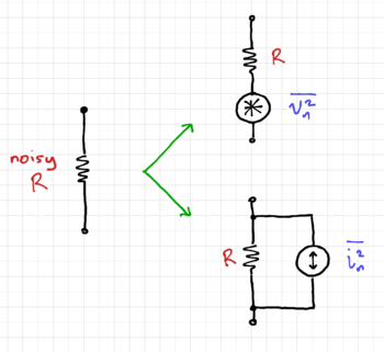
Consider the noisy resistor in Fig. 1. We can model this as a noiseless resistor in series with a voltage noise generator, or a noiseless resistor in parallel with a current noise generator. Since we cannot predict the voltage or current noise at any point in time, we can instead specify the noise mean square voltage spectral density over a unit bandwidth, :
-
(1)
-
Where is Boltzmann's constant, equal to and is the temperature in Kelvin. The total integrated noise power is then:
-
(2)
-
Where is the observation bandwidth. Alternatively, we can specify the total integrated noise power from the noise current generator:
-
(3)
-
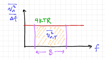
Thermal noise is white noise, since is constant over frequency, and hence the noise generators have white power spectral densities, as shown in Fig. 2. Just like any small signal, the shape of the power spectral density can be shaped by the frequency response of the rest of the circuit.
Also note that the polarity of the noise generators are intentionally not specified in the symbols shown in Fig. 1, since the noise voltage or current can take on positive or negative values at any given time.
For example, a resistor with at , the voltage noise power is:
-
(4)
-
Which gives us:
-
(5)
-
For a measurement bandwidth of , we get . This is the smallest voltage, or the minimum detectable signal we can resolve across this resistor with this bandwidth, i.e. the smallest voltage we can distinguish from the thermal noise of the resistor.
Noise in Resistor Circuits
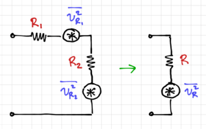
Consider two noisy resistors in series, as shown in Fig. 3. The equivalent resistance of the series circuit is , and since we can sum the voltage noise powers, we get:
-
(6)
-
It is important to remember that the noise power is additive, but the noise voltages and currents are not, since we do not know the phase of these signals at a given point in time. Similarly, for the parallel resistor circuit in Fig. 4, the equivalent conductance is , and the resulting equivalent current noise generator is:
-
(7)
-
In adding the noise powers, we assumed that the noise generators are independent of each other, i.e. the noise sources are uncorrelated. We will look at the case of correlated noise sources later.
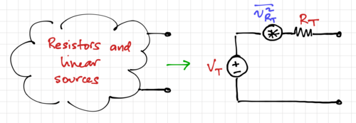
Extending these definitions to any arbitrary resistive circuit, we can determine the equivalent Thevenin or Norton equivalent circuit, as illustrated in Fig. 5, as well as the noise associated with the Thevenin resistance, , as:
-
(8)
-


